From Manuals
The following image shows where the connectors, headers, and jumpers are located on the Bambino 200.
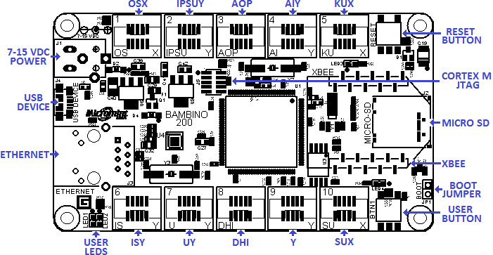
Bambino 200 User Interfaces, Connectors, and Jumpers
Power Supply
User Button and LEDs
USB Device
Boot Jumper
Socket 1 OSX
Table x.x: Gadgeteer Functions for Socket 1
| Socket Pin #
| Gadgeteer Function O
| Gadgeteer Function S
| Gadgeteer Function X
| MCU Symbol
|
| 1
| 3.3V
| 3.3V
| 3.3V
| 3.3V
|
| 2
| 5.0V
| 5.0V
| 5.0V
| 5.0V
|
| 3
| GPIO2[5]
| GPIO2[5]
| GPIO2[5]
| P4_5
|
| 4
| GPIO2[9]
| GPIO2[9]
| GPIO2[9]
| P5_0
|
| 5
| DAC
| GPIO2[4]
| GPIO2[4]
| P4_4
|
| 6
|
| SSP0_SSEL
|
| P1_0
|
| 7
|
| SSP0_MOSI
|
| P1_2
|
| 8
|
| SSP0_MISO
|
| P1_1
|
| 9
|
| SSP0_SCK
|
| P3_0
|
| 10
| GND
| GND
| GND
| GND
|
Socket 2 IPSUY
Table x.x: Gadgeteer Functions for Socket 2
| Socket Pin #
| Gadgeteer Function I
| Gadgeteer Function P
| Gadgeteer Function S
| Gadgeteer Function U
| Gadgeteer Function Y
| MCU Symbol
|
| 1
| 3.3V
| 3.3V
| 3.3V
| 3.3V
| 3.3V
| 3.3V
|
| 2
| 5.0V
| 5.0V
| 5.0V
| 5.0V
| 5.0V
| 5.0V
|
| 3
| GPIO1[0]
| GPIO1[0]
| GPIO1[0]
| GPIO1[0]
| GPIO1[0]
| P1_7
|
| 4
|
|
| GPIO3[3]
| U0_TXD
| GPIO3[3]
| P6_4
|
| 5
|
|
| GPIO3[4]
| U0_RXD
| GPIO3[4]
| P6_5
|
| 6
| GPIO2[6]
| GPIO2[6]
| SGPIO12
| GPIO2[6]
| GPIO2[6]
| P4_6
|
| 7
|
| SGPIO13
| SGPIO13
|
| GPIO5[12]
| P4_8
|
| 8
| SGPIO14
| SGPIO14
| SGPIO14
|
| GPIO5[13]
| P4_10
|
| 9
| SGPIO15
| SGPIO15
| SGPIO15
|
| GPIO5[14]
| P4_10
|
| 10
| GND
| GND
| GND
| GND
| GND
| GND
|
Socket 3 AOP
Table x.x: Gadgeteer Functions for Socket 3
| Socket Pin #
| Gadgeteer Function A
| Gadgeteer Function O
| Gadgeteer Function P
| MCU Symbol
|
| 1
| 3.3V
| 3.3V
| 3.3V
| 3.3V
|
| 2
| 5.0V
| 5.0V
| 5.0V
| 5.0V
|
| 3
| GPIO2[3]/ADC0_0
| GPIO2[3]
| GPIO2[3]
| P4_3
|
| 4
| GPIO2[1]/ADC0_1
| GPIO2[1]
|
| P4_1
|
| 5
| ADC1_0
| DAC
|
| ADC0_0/ADC1_0
|
| 6
| GPIO2[2]
|
| GPIO2[2]
| P4_2
|
| 7
|
|
| MCOA0
| P4_0
|
| 8
|
|
| MCOA1
| P5_5
|
| 9
|
|
| MCOA2
| P5_7
|
| 10
| GND
| GND
| GND
| GND
|
Socket 4 AIY
Table x.x: Gadgeteer Functions for Socket 4
| Socket Pin #
| Gadgeteer Function A
| Gadgeteer Function I
| Gadgeteer Function Y
| MCU Symbol
|
| 1
| 3.3V
| 3.3V
| 3.3V
| 3.3V
|
| 2
| 5.0V
| 5.0V
| 5.0V
| 5.0V
|
| 3
| GPIO3[12]/ADC0_4
| GPIO3[12]
| GPIO3[12]
| P7_4
|
| 4
| GPIO3[13]/ADC1_6
|
| GPIO3[13]
| P7_5
|
| 5
| ADC1_6
|
| GPIO3[15]
| P7_7
|
| 6
| GPIO3[14]
| GPIO3[14]
| GPIO3[14]
| P7_6
|
| 7
|
|
| GPIO3[10]
| P7_2
|
| 8
|
| I2C1_SDA
| GPIO5[3]
| P2_3
|
| 9
|
| I2C1_SCL
| GPIO5[4]
| P2_4
|
| 10
| GND
| GND
| GND
| GND
|
Socket 5 KUX
Table x.x: Gadgeteer Functions for Socket 5
| Socket Pin #
| Gadgeteer Function K
| Gadgeteer Function U
| Gadgeteer Function X
| MCU Symbol
|
| 1
| 3.3V
| 3.3V
| 3.3V
| 3.3V
|
| 2
| 5.0V
| 5.0V
| 5.0V
| 5.0V
|
| 3
| GPIO2[10]
| GPIO2[10]
| GPIO2[10]
| P5_1
|
| 4
| U1_TXD
| U1_TXD
| GPIO2[15]
| P5_6
|
| 5
| U1_RXD
| U1_RXD
| GPIO1[7]
| P1_14
|
| 6
| U1_RTS
| GPIO2[11]
|
| P5_2
|
| 7
| U1_CTS
|
|
| P5_4
|
| 8
|
|
|
|
|
| 9
|
|
|
|
|
| 10
| GND
| GND
| GND
| GND
|
Socket 6 ISY
Table x.x: Gadgeteer Functions for Socket 6
| Socket Pin #
| Gadgeteer Function I
| Gadgeteer Function S
| Gadgeteer Function Y
| MCU Symbol
|
| 1
| 3.3V
| 3.3V
| 3.3V
| 3.3V
|
| 2
| 5.0V
| 5.0V
| 5.0V
| 5.0V
|
| 3
| GPIO3[0]
| GPIO3[0]
| GPIO3[0]
| P6_1
|
| 4
|
| GPIO1[1]
| GPIO1[1]
| P1_8
|
| 5
|
| GPIO2[12]
| GPIO2[12]
| P5_3
|
| 6
| GPIO4[11]
| SGPIO8
| GPIO4[11]
| P9_6
|
| 7
|
| SGPIO5
| GPIO0[5]
| P6_6
|
| 8
| SGPIO6
| SGPIO6
| GPIO5[15]
| P6_7
|
| 9
| SGPIO7
| SGPIO7
| GPIO5[16]
| P6_8
|
| 10
| GND
| GND
| GND
| GND
|
Socket 7 UY
Socket 8 DHI
Socket 9 Y
Socket 10 SUX
Ethernet
MICRO SD
XBEE
NEXT: Mechanical and Electrical Characteristics
PREVIOUS: Hardware
